© Courtesy of Anagram Architects
Location: New Delhi, India
Design Team: Vaibhav Dimri & Madhav Raman
Client: South Asian Human Rights Documentation Centre
Site Area: 50 sqm
Project Area: 172 sqm
Project Year: 2005
Photographs: Courtesy of Anagram Architects
South Asian Human Rights Documentation Centre (SAHRDC) is a non-governmental organisation which seeks to investigate, document and disseminate information about human rights. A small office with limited resources, the SAHRDC also runs an internship programme attracting scholars from universities in India and abroad. It required an office to be made on a 50 sqm plot emphasising spatial efficiency and cost effective construction.
Design Generators
STREET CORNERThe site is at a busy street corner with essentially pedestrian traffic. As the site is not very large, the acoustic and visual intrusion of the street activity into work spaces was a key concern.
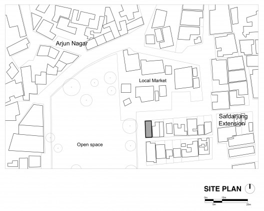
site plan
The method of construction adopted had to optimize the space available on site and a modest budget.
SOLAR THERMAL GAIN
The orientation of the site is such that the longer 10m side is exposed to direct sun throughout the day. Reducing the resulting solar thermal gain was an important design generator.
© Courtesy of Anagram Architects
Design response
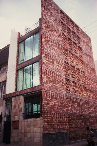
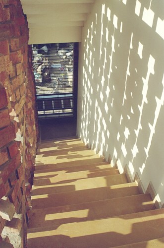
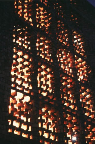
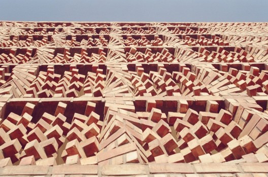
ENGAGING THE STREETAlthough some fortification against the street was required, it was crucial for the façade “converse” with the external activity. The external wall is conceived as an animated, dynamic skin reflecting the bustle of the street and activating what would otherwise have been a mundane façade with minimal fenestrations. The porosity of the wall maintains a degree of privacy while playfully engaging with the street corner.
SPACE AND COST OPTIMISATION:
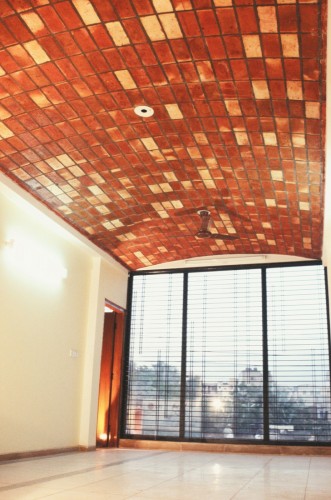
Efficient Space utilisation is achieved by creating a single consolidated volume on each floor to be flexibly partitioned as per the client’s requirements. This volume is serviced by a flanking buffer bay of a single flight cantilevered staircase and a toilet stack. Costs were minimised by using exposed brick construction and by creating a beamless soffit at every floor.
To create a beamless soffit without increasing the thickness of the slab, a gently vaulting roof was designed. Lateral inverted beams were introduced and flooring laid onto an infill so that each floor plate insulated eliminating the need for a false ceiling.
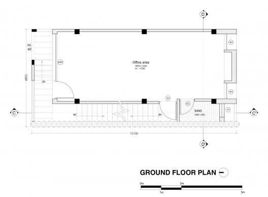
ground floor plan
© Courtesy of Anagram Architects
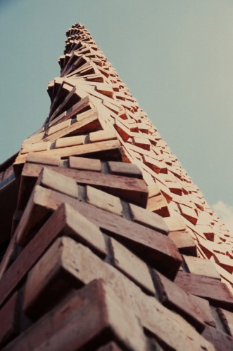
This buffer bay forms a breathing thermal barrier along the sun facing side. By situating the staircase and toilet stack in this bay, the internal workspaces are protected. The porosity of the wall ensures that the buffer bay is well ventilated and yet shaded so as to reduce the amount of heat transmitted to the workspaces. A single repeating brick module creates a visually complex pattern in the manner of traditional South Asian brise soleils.
The construction of the wall:
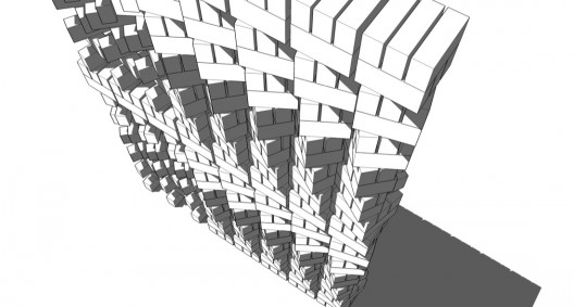
A six brick module is laid in staggered courses that create twirling vertical stacks and an undulating surface. The construction of the screen wall was a result of a five-week process devising masonry techniques on site. From verification of plumbline to the structural bonding of the brick courses, methods of brick laying were devised through a deep on-site collaboration between the masons and the architects.
© Courtesy of Anagram Architects
brick wall detail 02
High level of porosity in the central portion of the wall.
Effective horizontal bonding and load distribution between the bricks.
No visible intrusion of any material other than brick masonry onto the façade.
The repeating pattern modules must be complete end to end over the entire width and height of the wall i.e. there should be no deviation in the pattern.
Through computer modeling, the architects realized that a simple rotating module of bricks would create the kind of visual and textural complexity need to achieve the design objective of engaging the street corner.
© Courtesy of Anagram Architects
But using a 6 brick module created to very basic masonry concerns:
For proper alignment (prevention of corbelling), all the centres of the modules in a vertical stack had to fall on one perfectly vertical axis around which the module would rotate. This was difficult to estimate accurately on site during bricklaying (owing to human errors).
The other issue was verification of plumbness of every course. Dropping an accurate plumb line from one course to the next was not feasible since the brick faces were not in the same plane.
A single vertical stack was built and rebuilt five times on site with both the architects and the masons trying to co-strategise on a simple and practical brick laying technique that could be replicated by the various masonry teams without relying heavily on the individual skills of a master mason.
© Courtesy of Anagram Architects
The horizontal interlocking between modules essentially happens through the cross-stack overlapping of the central bricks in the modules. In the porous central portion of the façade, brickwork is reinforced horizontally by a laying a thin section (95mm X 125 mm) reinforced cement concrete beam along the cavity created by the missing central brick.
- © Courtesy of Anagram Architects
- © Courtesy of Anagram Architects
- © Courtesy of Anagram Architects
- © Courtesy of Anagram Architects
- © Courtesy of Anagram Architects
- © Courtesy of Anagram Architects
- © Courtesy of Anagram Architects
- © Courtesy of Anagram Architects
- © Courtesy of Anagram Architects
- © Courtesy of Anagram Architects
- © Courtesy of Anagram Architects
- © Courtesy of Anagram Architects
- © Courtesy of Anagram Architects
- site plan
- ground floor plan
- typical floor plan
- section 01
- section 02
- brick wall detail 01
- brick wall detail 02


